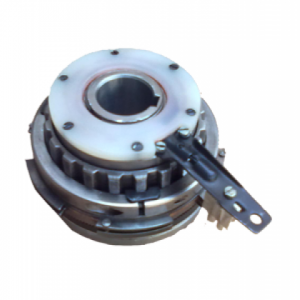


Description
M SERIES CLUTCH
Features
- Self-contained clutch designed for high-speed applications.
- Cam cage assembly engineered for optimum performance and increased capacity.
- Two ball bearings included supporting radial load and concentricity between races.
- Positive contact lip or felt seals provided for grease or oil lubrication.
- Tapped holes are machined on ends of the outer race for mounting auxiliary components.
- Metric bore and key-way available.
- Mounting accessories available.
Specifications
Bore Range: 0.500″ – 6.437″
Torque Range: 275 – 25,000 lb-ft


M Series clutches incorporate a dual ball bearing supported design that includes high-quality hardened, precision formed and finished steel cams in a cage. The cam cage assembly is engineered for optimum performance and increased capacity. This clutch design provides for the most custom configurable and versatile clutch offered in the industry.
The dual bearing design maintains race concentricity to help provide the most uniform loading of the cams. The M series clutch is designed to mount on through shafts that are secured to the shaft by a matching key provided with each stock bore clutch. Oil lubrication is standard, and grease lubrication is available at no additional cost. This general purpose clutch is intended for backstopping, indexing and overrunning (inner and outer race) applications.
There are four different versions: MG, MI, MR and MO, each customized to specific applications. A full line of accessories are also available to accommodate many different applications:
- couplings
- torque arms
- stub-shaft adapters
- oil reservoirs
Additional Data
| Model No. |
Torque Capacity |
Maximum Overrunning rpm |
Nominal Over- running Drag |
Stock Bores1 | ||||
| lb-ft. | N-m | Inner Race |
Outer Race |
lb-ft. | N-m | Inches | mm | |
| MG300A | 275 |
373 |
2900 | 800 | .17 |
0.2 |
.500 | 12.70 |
| MI300A | – | – | .625 | 15.88 | ||||
| MO300A | 3600 | 800 | .750 |
19.05 | ||||
| MR300A | 800 | 2900 | ||||||
| MG400A | 400 |
542 |
2700 | 800 | .21 |
0.3 |
.625 | 15.88 |
| MI400A | – | – | .750 | 19.05 | ||||
| MO400A | 3600 | 800 | .875 |
22.23 | ||||
| MR400A | 800 | 2700 | ||||||
| MG500A | 1175 |
1593 |
2400 | 750 | .38 |
0.5 |
.875 | 22.23 |
| MI500A | – | – | 1.000 | 25.40 | ||||
| MO500A | 3000 | 750 | 1.125 | 25.58 | ||||
| MR500A | 750 | 2400 | 1.250 | 31.75 | ||||
| MG600A | 2250 |
3051 |
1800 | 700 | .63 |
0.9 |
1250 | 31.75 |
| 1.375 | 34.93 | |||||||
| MI600A | – | – | 1500 | 38.10 | ||||
| 1.625 | 41.28 | |||||||
| MO600A | 2400 | 700 | 1.750 | 44.45 | ||||
| 1.937 | 19.20 | |||||||
| MR600A | 700 | 2100 | 2.000 | 50.80 | ||||
| MG600A | 5000 |
6779 |
1200 | 400 | 1.3 |
1.8 |
2.000 | 20.80 |
| MI600A | – | – | 2.250 | 57.15 | ||||
| 2.437 | 61.90 | |||||||
| MO600A | 2000 | 400 | 2.500 | 63.50 | ||||
| 2.750 | 69.85 | |||||||
| MR600A | 400 | 1750 | 2.397 | 74.60 | ||||
| Model No |
Torque Capacity |
Max.Over- running rpm |
Nominal Over- running Drag (lb-ft.) |
Stock Bores1 |
||||
| Ft-lbs. | N-m | Inner Race |
Outer Race |
lb-ft. | N-m | Inches | mm | |
| MG750 | 7000 |
9,491 |
1800 | 600 | |
3 |
2.437 | 61.90 |
| 2.500 | 63.50 | |||||||
| MR750> | 525 | 2600 | 2.750 | 69.85 | ||||
| 2.937 | <74.60 | |||||||
| 3.000 | 76.20 | |||||||
| MI750 | – | – | 3.250 | 82.55 | ||||
| 3.437 | 87.30 | |||||||
| MG800 | 13,000 |
17,626 |
1300 | 475 | 4.0 |
5 |
3.000 | 76.20 |
| 3.250 | 82.55 | |||||||
| 3.437 | 87.30 | |||||||
| MR800 | 475 | 2100 | 3.500 | 88.90 | ||||
| 3.750 | 95.25 | |||||||
| 3.937 | 100.00 | |||||||
| MI800 | – | – | 4.000 | 101.60 | ||||
| 4.250 | 107.95 | |||||||
| 4.437 | 112.70 | |||||||
| MG900 | 18,000 |
24,405 |
1200 | 400 | 5.0 |
7 |
4.000 | 101.60 |
| 4.250 | 107.95 | |||||||
| 4.437 | 112.70 | |||||||
| MR900 | 400 | 1850 | 4.500 | 114.30 | ||||
| 4.750 | 120.65 | |||||||
| 4.937 | 125.40 | |||||||
| MI900 | – | – | 5.000 | 127.00 | ||||
| 5.250 | 133.35 | |||||||
| 5.437 | 138.10 | |||||||
| MG1000 | 25,000 |
33,896 |
1200 | 325 | 6.0 |
8 |
5.000 | 138.10 |
| 5.250 | 133.35 | |||||||
| 5.437 | 138.10 | |||||||
| MR1000 | 325 | 1600 | 5.500 | 139.70 | ||||
| 5.750 | 146.05 | |||||||
| 5.937 | 150.80 | |||||||
| MI1000 | – | – | 6.000 | 152.40 | ||||
| 6.250 | 158.75 | |||||||
| 6.437 | 163.50 | |||||||